
Previewing geometry
Morphé shows geometry in two places: Rhino's viewport shows it as a mesh or as curves, and the window of Preview Field 3D draws an implicit straight from its formula on the graphics card, without meshing it.
Previewing in Rhino's viewport
Morphé Components can be previewed in Rhino's viewport: a 3D implicit as a shaded mesh of its surface, and a 2D implicit as its outline curves. A scalar volume previews as a shaded mesh of its surface, at its own voxel size. A field has no bounding box and no preview: bound it with  Implicit From Field, or view it with
 Preview Field 2D or
 Preview Field 3D. Turn a component's preview on or off with Preview on its right-click menu, as with any Grasshopper component.
Morphé draws these shaded meshes only in a shaded display mode, such as Shaded, Rendered or Arctic. If the preview of an implicit or a scalar volume does not appear, switch the viewport to one of them.
To see a preview in Wireframe, switch on Grasshopper's mesh-edge preview with Ctrl+M on the Grasshopper canvas. The preview then draws the edges of its mesh, and an implicit also draws its bounding box as an aqua box. Press Ctrl+M again to switch the edges off.
Preview resolution
The preview mesh of an implicit is built at a resolution of its own, which is automatic by default: a voxel size equivalent to a fiftieth of the diagonal of its bounding box, or, in the case of  Implicit From Scalar Volume, the voxel size of the volume.
To set it, right-click the component. The menu holds a box that reads Automatic. Type the voxel size the preview should use, in model units, and press Enter. A smaller value shows finer detail and takes longer to draw. To return to automatic, type -1 and press Enter: any value of 0 or below does the same. The setting is saved with the definition.
Preview Field 3D
Preview Field 3D opens a window that draws an implicit or a field on the graphics card, straight from its formula, without meshing it. The picture follows every change upstream, so the window is the place to work while you design. Mesh once the shape is settled.
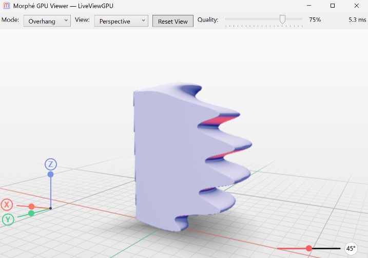
Each Preview Field 3D component has a window of its own, so several can be open side by side. The window opens the first time the component receives a field, and stays open until you close it or delete the component. A closed window opens again the next time the component runs. When several fields are connected, the window only shows the first.
Inputs
| Input | What it does |
|---|---|
Field |
The geometry to draw: an implicit or a field. Draw a scalar volume through Implicit From Scalar Volume. |
Scene Bounds |
A box. The window shows only what lies inside it, with the cut faces drawn solid, and frames the camera on it. Moving the box updates the picture at once. Leave it empty to frame the geometry itself. |
Build Direction |
The direction the part is printed in, for the Overhang mode. The default is world +Z. |
Grid Size |
The size of a cell of the grid on the ground, in the document's units. Leave it empty for a round size picked from the scene, about fifteen cells across; 0 hides the grid lines. |
Dark Mode |
Draws the window on a dark background when True. The default is False. |
An implicit carries its bounding box into the window: the camera frames the box, the section planes span it, and the ground lies under it. A field has no box, so the window frames it automatically and its section planes do not respond. Connect a box to Scene Bounds, or give the field a box with Implicit From Field.
Moving the camera
| Action | Result |
|---|---|
| Right-drag | Orbit |
| Shift + right-drag | Pan |
| Scroll wheel | Zoom |
| Reset View | Frame the geometry again |
The camera frames the geometry once, and then stays where you leave it while you edit the definition. Reset View frames the geometry as it is at that moment.
The top bar
- Mode chooses how the surface is coloured: 3D Shaded, Overhang, Thickness or Normals, described below.
- View switches between Perspective, the default, and Orthographic. The camera keeps its framing and its angle.
- Reset View frames the geometry again.
- Quality sets how finely each ray is traced to the surface, from 5% to 100%, with 55% as the default. A higher value draws dense lattices and tight twists cleanly, and draws more slowly. A lower value draws faster and can leave speckles on such shapes.
- The status bar, at the right end, gives the time the last frame took to draw, in milliseconds. It reads Starting while the window opens the graphics card.
Resolution and speed
The window draws at the size of its canvas, in pixels, so a larger window draws a finer picture and takes longer over each frame. While you orbit, pan, zoom, drag a slider or edit the definition, the window draws at a quarter of its width and height to keep up, and returns to full resolution after you stop.
Quality is the setting that trades detail for speed. A scalar volume is drawn from its voxels. A volume too dense to fit on the graphics card is left out of the picture, and the window says so: connect a box to Scene Bounds to preview a region of it. Meshing is not affected.
Display modes
3D Shaded is the standard display mode, where the geometry is rendered with basic lighting.
Overhang paints the downward-facing surfaces that need support when the part is printed along Build Direction. The slider at the bottom right sets the self-supporting angle, measured from the build plate, from 0° to 90°, with 45° as the default. Downward-facing surfaces whose angle is below the specified angle are painted coral. At 0° nothing is painted, and at 90° every downward-facing surface is.
Thickness measures the wall at each visible point, across the solid to its far side, and paints thin walls. The two boxes either side of the colour bar at the bottom right set the range, in the document's units. Walls at the lower value or thinner are coral, blending to the part's colours at the upper value and above. The range starts at 0.1 to 1.
Normals colours the surface based on the Z component of its normal.
Sectioning the model
The gizmo at the bottom left shows the model's X, Y and Z axes as the camera sees them. Each axis carries a handle that moves a cut plane across the model's box.
| Handle | Cut plane |
|---|---|
| X | A YZ plane, across the X axis |
| Y | An XZ plane, across the Y axis |
| Z | An XY plane, across the Z axis |
Drag a handle with the left mouse button towards the origin and watch the corresponding cutting plane move through the model, removing each time a larger section. Clicking on the letter at the end of an axis flips the section on display. The three planes can cut at the same time, with the cut faces drawn solid.
The planes span the box the window holds: the Scene Bounds box when one is connected, or otherwise the implicit's box, fitted closely to its surface. A field with no box has no section planes. The cuts stay where you leave them while you edit the definition.
Messages
Longer messages appear in a panel in the middle of the window:
- Preparing the preview... while the window prepares a new kind of scene for the graphics card, which can take a few seconds the first time.
- Scalar Volume too dense to preview whole, or too dense to preview in this box, with the volume's size and the limit, when a volume is left out of the picture.
- The reason the window could not start.
When no graphics card with DirectX 12 or Vulkan support is found, the window draws in software, far more slowly. Its title then ends in "(software renderer)", and the component shows a warning. When the window cannot start at all, the panel gives the reason, and the component shows it as an error. The graphics cards Morphé supports are listed under Requirements.
Sections in Rhino's viewport
Three components draw a flat section in Rhino's viewport, for reading values across a plane:
- Preview Field 2D draws a section of a field as a smooth colour-mapped slice, with distance contours on top.
 Preview Scalar Volume draws a section of a scalar volume as coloured cells. Cells outside the volume's narrow band are transparent.
 Preview Vector Volume draws a vector volume as arrows sampled on a section grid.
Each of them samples the rectangle connected to Rectangle, with Resolution samples across its width. Leave Rectangle empty to section the bounding box of an implicit or a volume along a plane chosen on the right-click menu, Section: XY plane, Section: XZ plane or Section: YZ plane, at the position Section gives, from 0 to 1 across the box. A field has no box, so Preview Field 2D needs a rectangle for it. The right-click menus of Preview Field 2D and Preview Scalar Volume also switch the colour bar and the contours on and off.